PCB tools
Here are the scripts I use to convert PC boards from Kicad to G-code.http://www.lwill.net/downloads/boardtools-01.tar.gz
This is the README included for information.
README 03/28/20012


Tested with LinuxCNC 2.6.0~pre and KiCad (2012-01-19 BZR3256)-stable and

    pcb2gcode 1.1.4


### DISCLAIMER ###

CNC MACHINES CAN BE DANGEROUS!!!

THOROUGHLY CHECK AND TEST ANY CODE BEFORE RUNNING!!!


Files included in boardtools directory:

doall.py                    GUI front end for pcbbatch

pcbbatch.py                 Batch file to run all programs using config file

boardcfgdef.py              Default config file

Etch_Z_adjust.2.2.cl.py     Modified command line version

gerber2emc2cl.py            Modified command line version

p2gdrillopt.py              For optimizing drill files

p2gpathopt.py               For optimizing paths

demo                        Directory with sample Kicad layout, gerbers, and

                            sample boardcfg.py for testing


REQUIRED:

python-argparse

pcb2gcode installed on system

EMC2/LinuxCNC 2.5+

KiCad


Optional:

opti  (from Etch_Z_adjust)  Untested, I have not used it, not included


-Quick and dirty:

Extract.

For GUI, from boardtools directory run:


$python doall.py


    You will probably need to run doall.py at least once to verify default

    file paths. Save defaults to boardcfgdef.py in installed directory.


To try demo:

    Click "Load boardcfg"

    Open the demo directory and choose boardcfg.py

    Click "Default Paths" and set to the correct locations.

    Click on "Browse" under "Board back" and reselect "demo-Back.gbl"

        to make sure the path is working directory is correct.

        This will automatically set the other files correctly.

    Click "Run boardcfg" (it will automatically ask you to save)

    Check out the generated files!


To run a config file from a project directory:


$python boardcfg.py


-The idea:

Generate ready to run g-code files from KiCad for LinuxCNC using one interface.


-The method (how I do it):

Schematic and board layout with KiCad.

    I use the Comment layer for text and draw board outline using actual tool

    path based on the bit I will be using so I can leave gaps to keep boards

    paneled together. (there is an option to use pcb2gcode for outline instead)

Generate gerbers and drill files (4). *Back.gbl, *PCB_Edges.gbr, *Comments.gbr,

    and *.drl

Use pcb2gcode to generate back and drill g-code files.

    * the paths are very "stair-steppy" which I did not like

Use gerber2emc2cl to generate text and outline g-code files.

Join the paths and text together in one file.

Use p2gpathopt to reduce "stair-step", smooth paths, and reduce moves.

    Due crude optimizing.

Use p2gdrillopt to due crude optimizing and optionally use only one drill bit.

Use Etch_Z_adjust (*modified) to do auto-leveling.


-The Solution:

Have a config / batch script to do all this automatically.

    In reality there is a script that is placed in the drawing directory

    that holds the configs (boardcfg.py) and calls another script (pcbbatch)

    that does all the hard work. This way boardcfg can be run in place when

    a board is modified without copying main script to each drawing directory.

    All needed settings needed to run are saved in the boardcfg.py file.

A GUI to select all the various setting and generate the config file and

    optionally run it.

Config file default name is boardcfg.py This can be modified by hand "at own

    risk" if desired, but may break compatibility with GUI. Undocumented.


-What does the work:

pcb2gcode


Etch_Z_adjust.2.2.cl.py

    Modified command line version. Added ability to re-run file without

    re-probing. Modified to use a separate probe instead of tool bit, and to

    set tool height automatically.(Must use EMC2/LinuxCNC 2.5+!!!!!! uses G10)

gerber2emc2cl.py

    Modified command line version. Added ability to mirror and offset.

p2gdrillopt.py

    For optimizing drill files. Allows using only one drill and does crude

    optimizing using Morton number.

p2gpathopt.py

    For optimizing paths. Smooths out pcb2gcode paths by finding the midpoint

    of each stair-step, eliminates redundant points creating straight lines

    within a set tolerance. (difference in slope < .001 or about .057 degrees)

    Adds very slight deviations from original, but gives much smoother result.

    You decide.

    Also optimizes based on Morton number.


-Credit where credit is due:

While thoroughly hacked and mangled, my work is based on these previous works.

Both have no copyright/left restrictions in the files.

I likewise put no restrictions other than ask for credit if you use it.

(Please visit lwill.net)


Etch_Z_adjust from michael_m at cnczone.com

http://www.cnczone.com/forums/pcb_milling/82628-cheap_simple_height-probing-11.html#post843483


gerber2emc2 from SAMMEL Lothar on the LinuxCNC wiki

http://wiki.linuxcnc.org/cgi-bin/wiki.pl?Converting_Tools


-Other software:

KiCad

http://kicad.sourceforge.net/wiki/Main_Page


LinuxCNC

http://www.linuxcnc.org


pcb2gcode

http://sourceforge.net/apps/mediawiki/pcb2gcode/index.php?title=Main_Page


-Why my settings / method seems weird:

I actually use a coated board and a drag bit to scribe the coating, then drill

    it without removing it from the machine, then etch in FeCl. The scribe

    only needs to be offset .001. The scribe and probe mount off to the side

    of my spindle, that is the reason for the offsets. I also use

    Etch_Z_adjust for engraving other things using a normal engraving bit and

    separate probe which was the original reason for modifying it.

I used the Morton number optimizing method because it was fast and simple and

    better than nothing. I may rewrite the optimizing method later.

This is my first major attempt at Python programming, so it is ugly. It

    started simple, and 1100+ lines of code later.... So don't ask why I did

    something the way I did, the answer you will likely get is

    "Because it worked!"

More info on this and other stuff at lwill.net/blog

All comments are welcome, but I reserve the right to ignore them!


I can be contacted though lwill.net
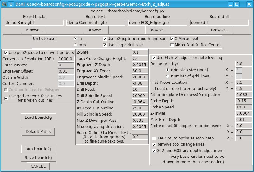
Screen shot of GUI:
Comments - Edit - Delete
PC Boards, My Way
I have found a new way of making PC boards.I start with a bare board.
Place a thin layer of "secret" resistant coating on it.(on a spin coater)
Use my CNC router to "engrave" it with a drag scribe.
With out moving it, drill it and route outline.
Last etch it in ferric chloride.
Now this may seem odd at first. Why not just route the board with the CNC?
Let me try to explain. I have always used the photo resist method with laser transparencies and pre-sensitized boards, etched then drilled. When all goes well, the results are great. The biggest problem has always been getting a good 1 to 1 print from the laser printer. Next problem is lining the board up to drill it, which gets worse if the print was not square or to scale to begin with.
Now, my main reason is I am sorta cheep. I have never bought the right bits to do direct PCB routing. My router does pretty good, but I am just not sure how it would do, and hate to spend money just to break bits. I like the photo method, but bare boards are cheaper. There is also the fact I already have a bubble tank of etchant.
When I first started experimenting with my method I used an old photo board I had. It was a bit old, so I just tossed it in developer with out exposing it to fix the resist first. This worked, but still expensive board and the coating is very fragile and gets scratched during drilling. More on the coating later.
Next I made a drag engraving point out of an old carbide bit. I tried various angles and about 90 deg. works well. I mounted the point in a solid tool holder off to the side of my spindle, which is just a Rotozip, and while still fairly tight, does have a bit of play. Since I would be dragging and not spinning the bit I saw no reason to put the strain on the bearings or risk unnecessary flexing error. The bit holder is also longer than the spindle so I can leave my drill bit in and install and remove the holder between steps. (I have the offset set in EMC2)
I mount the board on a piece of "foam core" sign board with double face tape like used on window film. It is very thin and very sticky. This is then stuck to my table. This gives me a well supported board with the foam core having just a bit of give and acts as a waste board underneath for drilling.
I then run my code for the trace outlines. I use Kicad with pcb2gcode, but have came up with some scripts I will get into in another post* for generating my files and getting good results. I also incorporate a modified version of Etch_Z_Adjust to keep my depth consistent. I replace my scribe with a touch probe made from a micro switch and probe the surface first. I then replace the scribe and use a depth of .0015" which scores though my coating and leaves a fine line in the copper.
Now I remove the scribe and reset for drilling. Since nothing has been moved, everything is already lined up.
Last I do any cutout routing I want for the board shape.
Once finished on the CNC it is into the ferric chloride . Here one of the complaints often heard about FeCl is actually put to use. The scribe lines are very fine, but since I lightly scored the copper, a small amount of undercutting occurs, widening the lines slightly.
Does it save me any time? Well, I have ran 1.5" X 6" boards with 162 holes that take less than 10 minutes to engrave at 20 in/min. Compare with 8~12 min. exposure time and then developing, that is not bad when I do not have to realign for drilling. Etching is also quicker since I am not removing as much copper. Doing multiple boards takes longer of course, but if I make a mistake, only one gets screwed up and not a whole panel. I can also run different boards at the same time without having to make new films.
Once I was able to get good results, I wanted to stop using pre-sensitized boards and started looking for a coating that would work. I also needed a way to apply it consistently. I tried spray paint. Worked, but not consistent and had to be removed at the end. Tried various clear coats, polyurethane, stains, and wax with mixed results. One big problem was even coating without bubbles or dust. (like most people, I don't work in a "clean" room!)
The "secret" coating I found: Future vinyl floor finish! (now sold under the Pledge with Future name)
Apparently, model builders have been using it for years to coat windshields and protect decals. It is tough! Dries FAST. Nontoxic. And last, CHEEP! I add a little food coloring to make it easier to see, and a bit of alcohol to thin it just a bit. Oh, and you can easily clean it up with an ammonia based window cleaner!
Now to get it on the board. I built a spin coater. A motor and a spinning disk. My first small attempts I used a muffin fan with a pot to control the speed and got good results. I up sized and can now handle a 6" X 9" board inside a bucket to contain the mess. I control the speed using EMC2 and a spare high current output on my CNC's BOB. I came up with some custom M codes and a HAL file that let me control it like a spindle using PCM and can set the acceleration. I can now write a program to start slow while I apply the coating, spin up gently to throw off the excess, slow down to let it level and start to set, then spin the hell out of it and hit it with a heat gun to dry. The process is very quick and in less that 5 minutes I have a dry board ready to go, hardly enough time for dust to even settle on it if it could.
Added benefit, when the board is done, the coating is so thin it can be soldered though without removing it first and it protects the rest of the traces from corrosion.
*I will be doing another post on the scripts I use once I clean them up a bit.
*I will also be adding pictures the next time I run boards. I wanted to get this written up while I had a chance.
Comments - Edit - Delete